Plate Inspection
Rolled aluminum and titanium plates intended for aerospace applications are inspected in accordance with stringent industry standards. The large size of the plates and their wide thickness range demand high inspection productivity. Defect evaluation and comprehensive inspection reports are common requirements.
ScanMaster offers a variety of field proven, high throughput plate inspection systems designed to provide a complete solution for material testing and handling. ScanMaster systems use either phased array or conventional transducers for defect detection, and include advanced features for plate scanning, data acquisition, defect evaluation and reporting.
Plate Inspection: Systems Gallery
Rolled aluminium plates intended for aerospace applications are inspected in accordance with stringent industry standards, such as the AMS-STD 2154, the ASTM B594 and the Boeing BAC 7055. The large size and considerable thickness of the plates demand high inspection productivity. Defect evaluation and categorization, comprehensive inspection reports, and interfaces to various MES (manufacturing execution system) types are common requirements.
Automation of standart-driven functions:
- Non-contact surface tracking
- Automated UT calibration and verification procedures to reduce pre-scanning time
- Generation of beam profile data for accurate sizing of defects
- A configurable defect evaluation procedure complying with applicable standards, using a fully automated rescan
- Automated defect classification and sizing
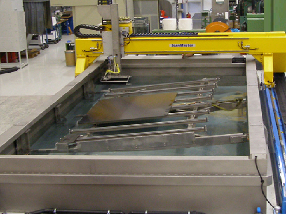
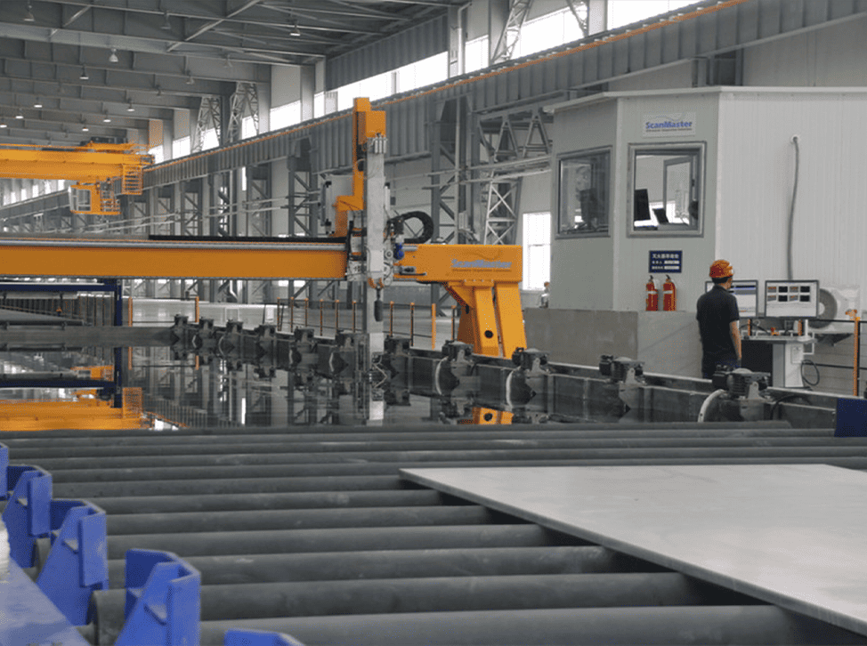
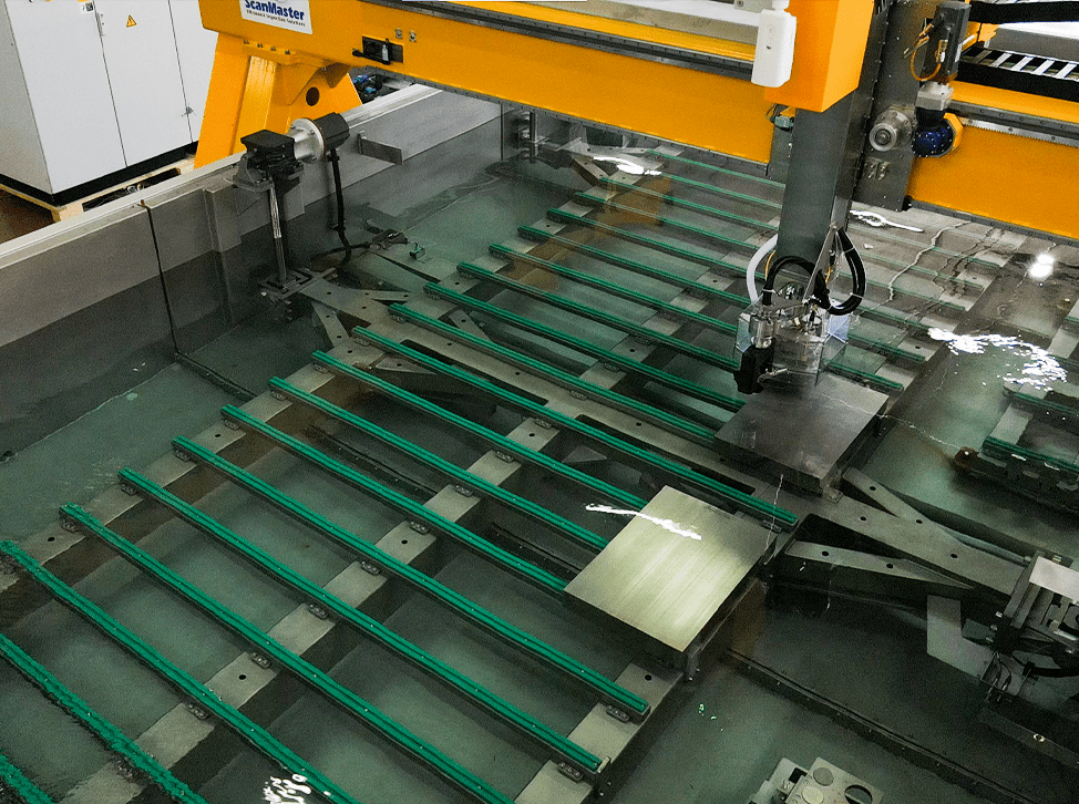
The System
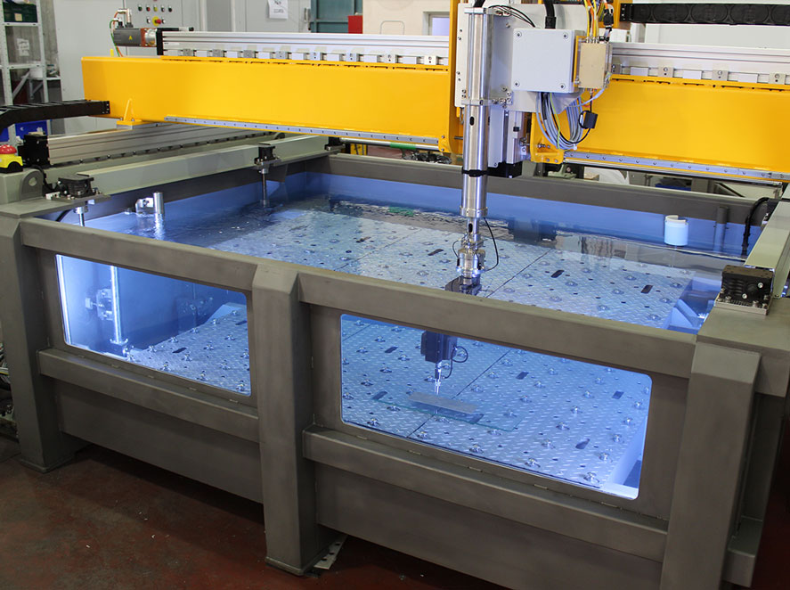
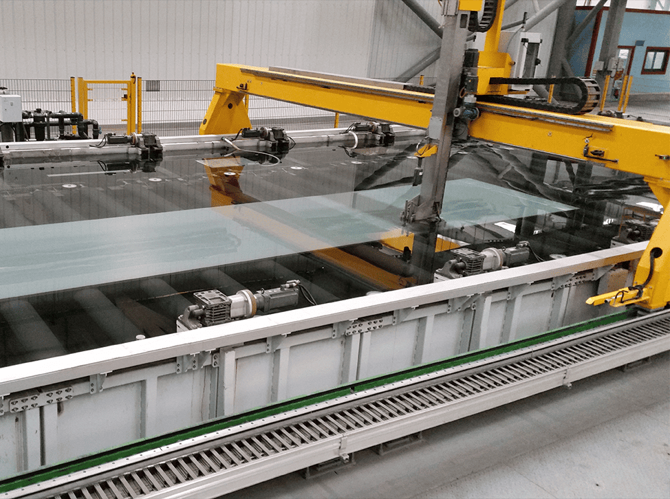
The inspection system design is based on a loading roller table, from where the plates are transported onto the lifting platform and immersed into the tank. After inspection, the plates are lifted up and proceed through the dryer to the unloading table.
UT inspection is done in immersion based pulse-echo mode using two 128 element phased array transducers that scan simultaneously with the required overlapping.


Automated UT calibration and verification procedures to reduce pre-scanning time
Sensitivity calibration and verification procedures are among the most time consuming processes of UT inspection.
The initial stage involves setting the uniformity of the virtual probes’ (VP) ultrasonic beams across the depth, using a reference block with side-drilled holes of different depths. As the system operates with two probes, this procedure is extremely important.
Once VP uniformity is achieved, Distance Amplitude Correction (DAC) calibration and verification is automatically performed for a single VP by dynamically scanning a designated set of calibration standards. Once the DAC is created, the system automatically updates it in all setups, as necessary. The sensitivity check (dynamic check) is usually done every four hours and is executed automatically.
Automatic inspection procedure
1. The Main Scan
The main scan begins after the plate is inside the tank and the "Clearance" command is received. The main scan is done using a UT setup for the required inspection class. C-Scan images of the material gate and back-wall gate (with separate attenuation mode) are collected.
Based on this scan, the software generates an intermediate report that shows detected indications on the C-scan. The Indications table of the report includes details about the location, amplitude and ToF of each indication, and provides a preliminary list of indications with defect categorizations according to the guidelines of the relevant standard.

2. Indications rescan
Following the main scan, some of the indications found in the plate need to be rescanned.
According to ASTM B594 2.2.1 and 10.5.1 specifications and Boeing specifications, all indications exceeding a predefined level of the adjusted reference size must be inspected by means of angle manipulation. This evaluation is done by angulation and movement of the sound beam around the indication.
In systems based on conventional UT probes, this inspection is generally done using a probe manipulator that mechanically rotates the probe. In the system described in this paper, the phased array probe performs the procedure using a combination of electronic sectorial and linear scanning.
The procedure generates a combined "Top C-Scan".
Defects can be evaluated one at a time, or automatically (as a set). Following the evaluation process, the Indications table is updated with the maximum acquired amplitude of the defect and its proper categorisation.
")
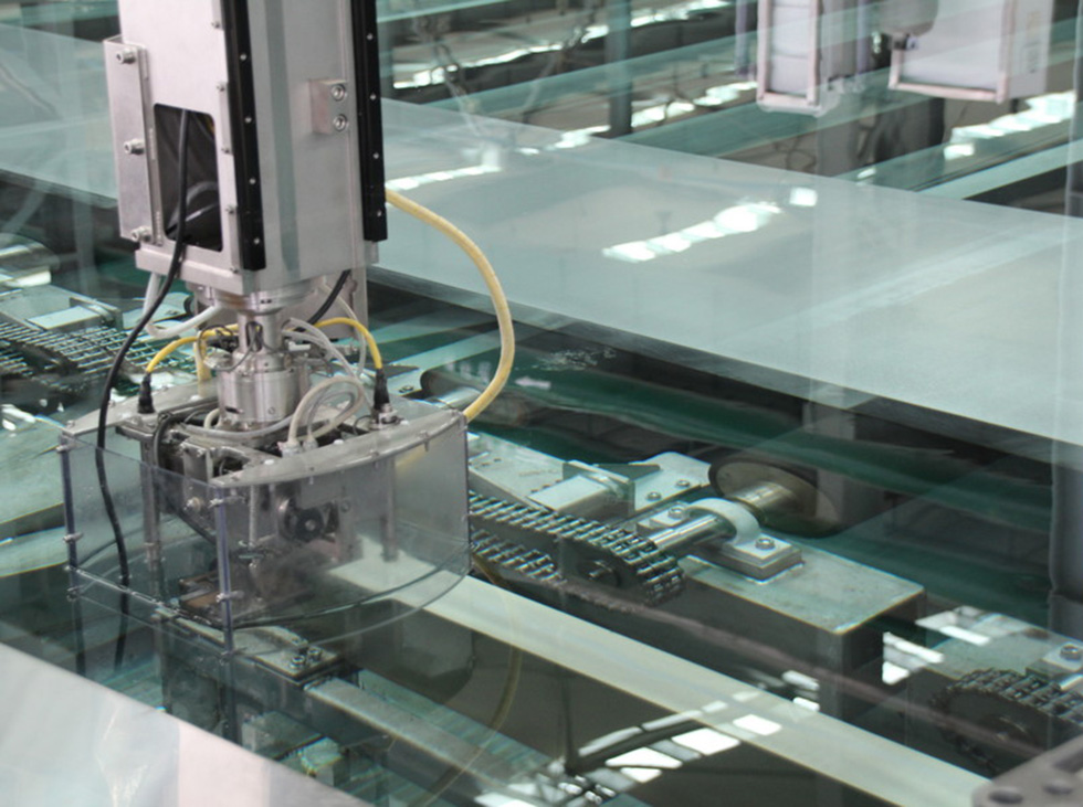
Plate Surface Tracking
Due to the production process of these plates, there may be occasional slight waviness of the plate surface that affects the UT refraction angle. Misalignment of plate placement relative to the scanning gantry may also affect the relative position of the plate surface to the transducers’ scanning plan. To prevent misalignment issues from influencing the UT data, the system tracks the surface of the plate during scanning, using a specially designed surface tracking subsystem.
Distance monitoring is based on measurement of the water path of each of the three probes to the inspected surface. A designated software algorithm monitors the distance and calculates the offsets to be applied to the azimuth or elevation axis of the manipulator. In addition, the software generates the necessary offset to be applied to the Z axis in order to maintain the water path within a predefined tolerance.
Use of the surface following algorithm does not affect scanning speed.
In order to utilize the full scale of the system scanning envelope while maintaining high productivity, the system supports inspecting multiple plates of the same thickness in one scan. During the multi-plate full scan, one C-scan of all the plates scanned in a batch is produced. After the scan is finished and the overall C-scan has been completed, the software automatically divides the overall C-Scan into separate C-scan files of each plate. To prevent data loss, the division is done using an edge recognition algorithm. The separate C-Scans therefore include part of the edge and the stretcher marks (if any).
The operator may define the ROI (Region of Interest) of a C-scan of an individual plate to define an area in which defect evaluation will be done. From this point, each plate is evaluated separately, and an individual report per plate lot number is issued.
")
Features and Benefits
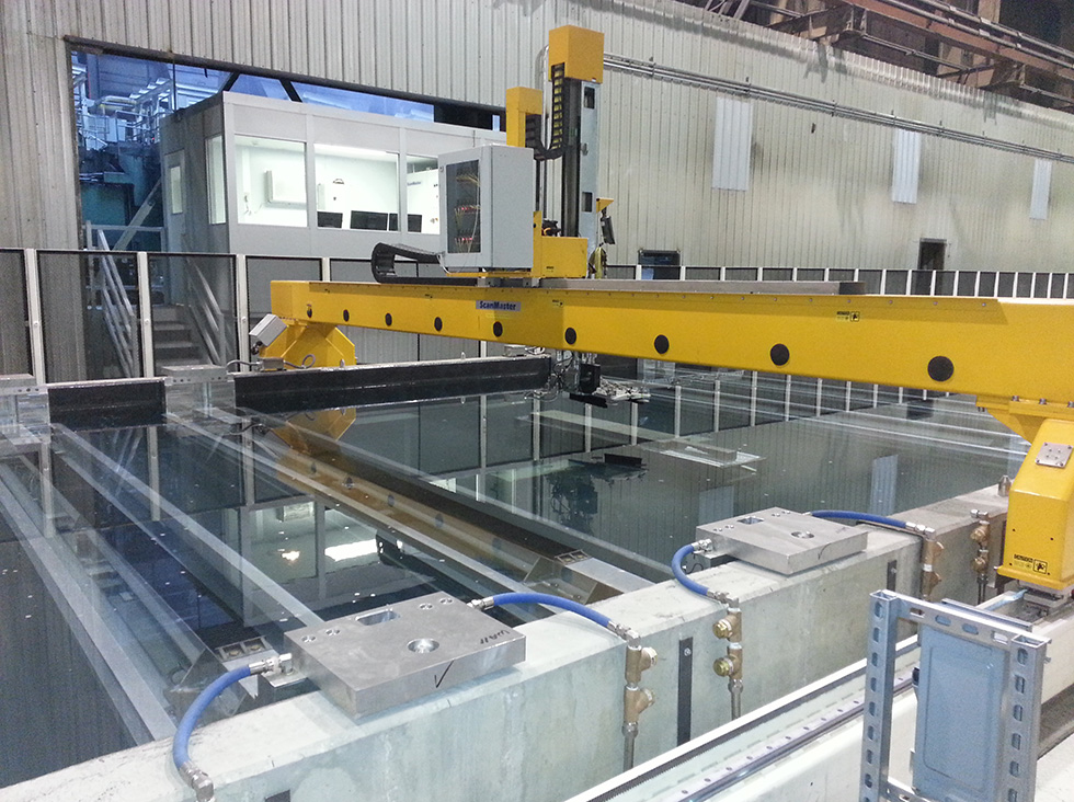
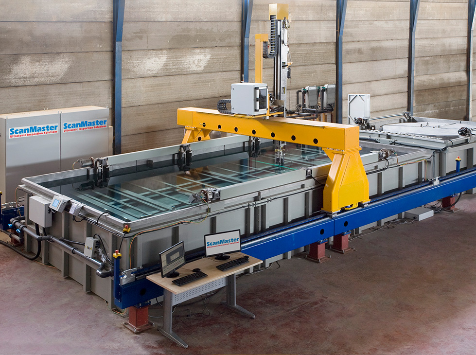
- ‘One stop shop’ providing fully integrated, high throughput automated inspection systems.
- To provide a comprehensive inspection solution, systems may include material handling devices such as lifting platforms and rolling tables in addition to the immersion tank and scanning robot.
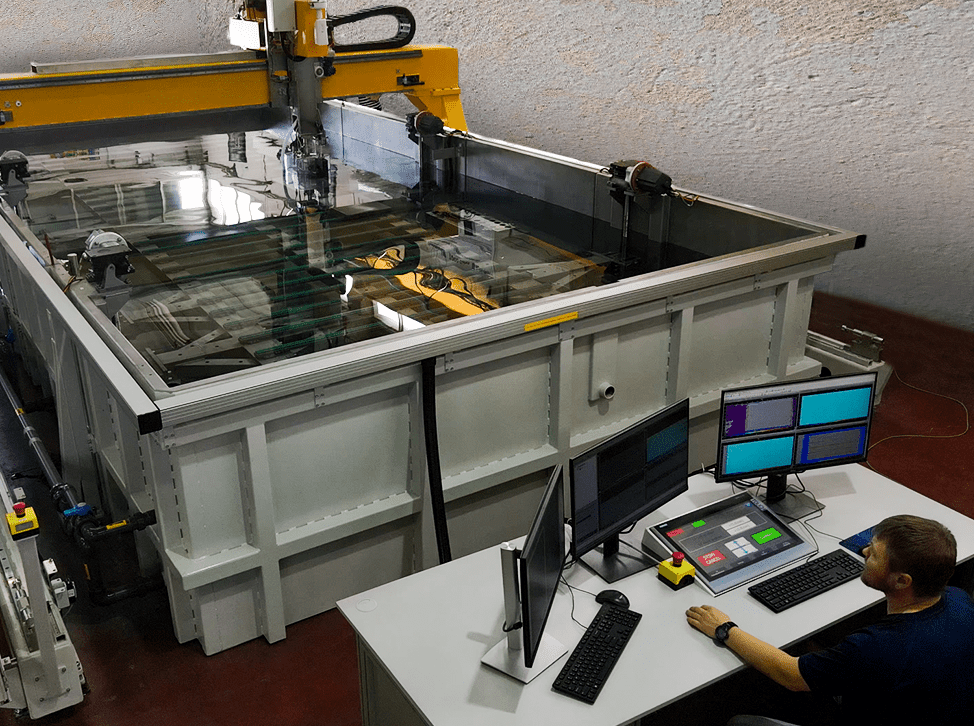
- Full communication with plant computer for material handling, transfer of material information and test requirements, and handover of inspection results.
- Advanced, unique features assure accurate scanning, reliable data acquisition and automated defect evaluation, as well as high inspection throughput.
- Automated DAC calibration to reduce pre-scanning time.
- Non-contact surface tracking to ensure perpendicularity of the ultrasonic beam on the plate surface.
- Automated defect evaluation procedure complying with applicable standards.
- Compliance with major standards, such as AMS STD 2154, ASTM B 594, ASTM E 2375, BSS 7055 and ABP-6-5232.