Ultrasonic Bearing Inspection
Ultrasonic Bearing Inspection
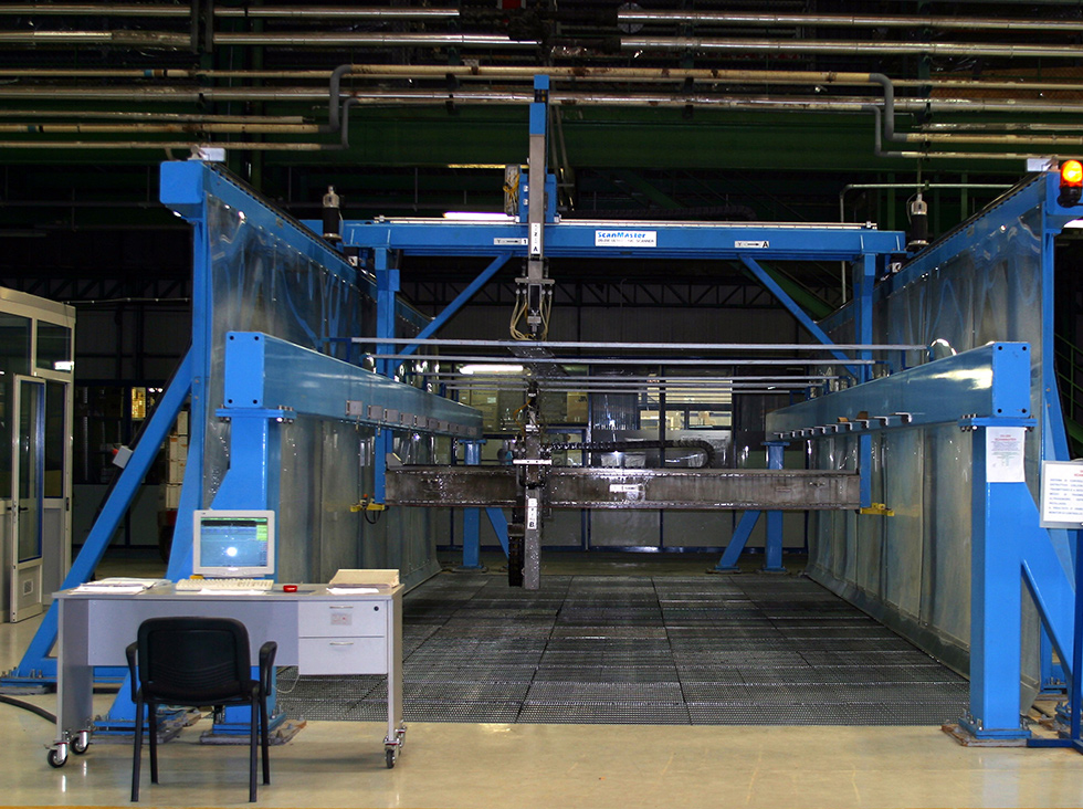
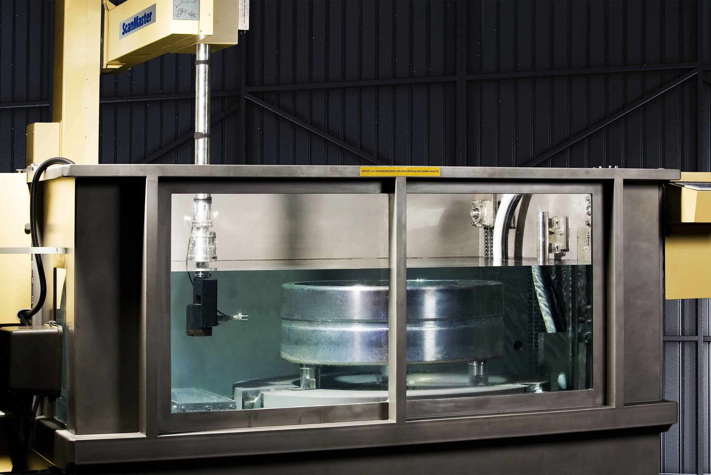
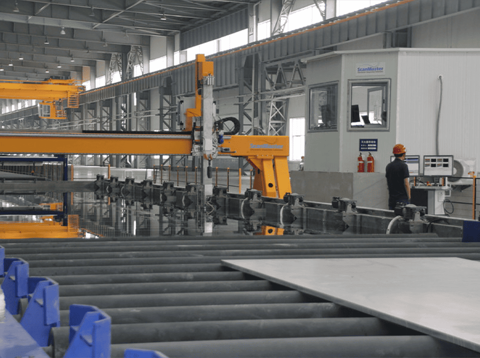
ScanMaster has enhanced and adapted its line of immersion scanners to meet the stringent inspection requirements set by the bearing industry.
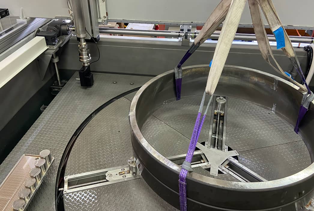
ScanMaster immersion scanners service the full range of industrial bearing rings, from those used in high-speed trains to those integrated in windmills. These fully integrated, high throughput automated ultrasonic bearing inspection systems provide the best bearing inspection solution, both performance- and productivity-wise.

Ultrasonic Bearing Inspection
ScanMaster has enhanced and adapted its line of immersion scanners to meet the stringent inspection requirements set by the bearing industry.
ScanMaster immersion scanners service the full range of industrial bearing rings, from those used in high-speed trains to those integrated in windmills. These fully integrated, high throughput automated ultrasonic bearing inspection systems provide the best bearing inspection solution, both performance- and productivity-wise.
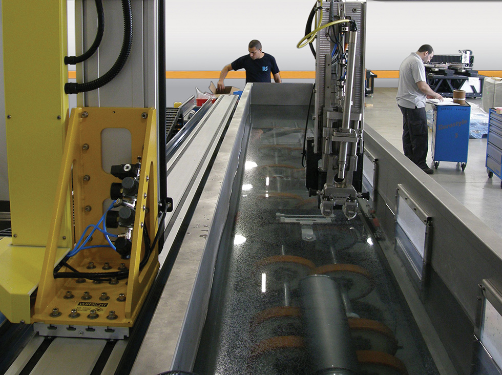
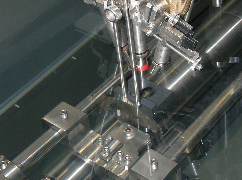
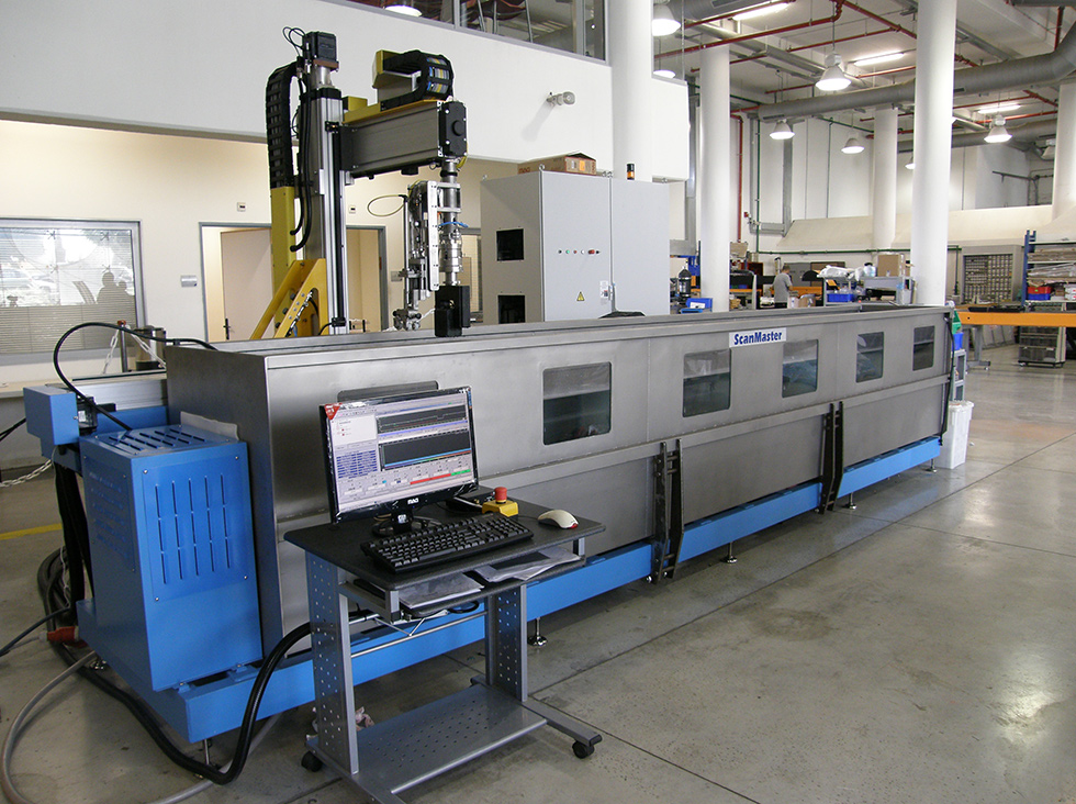
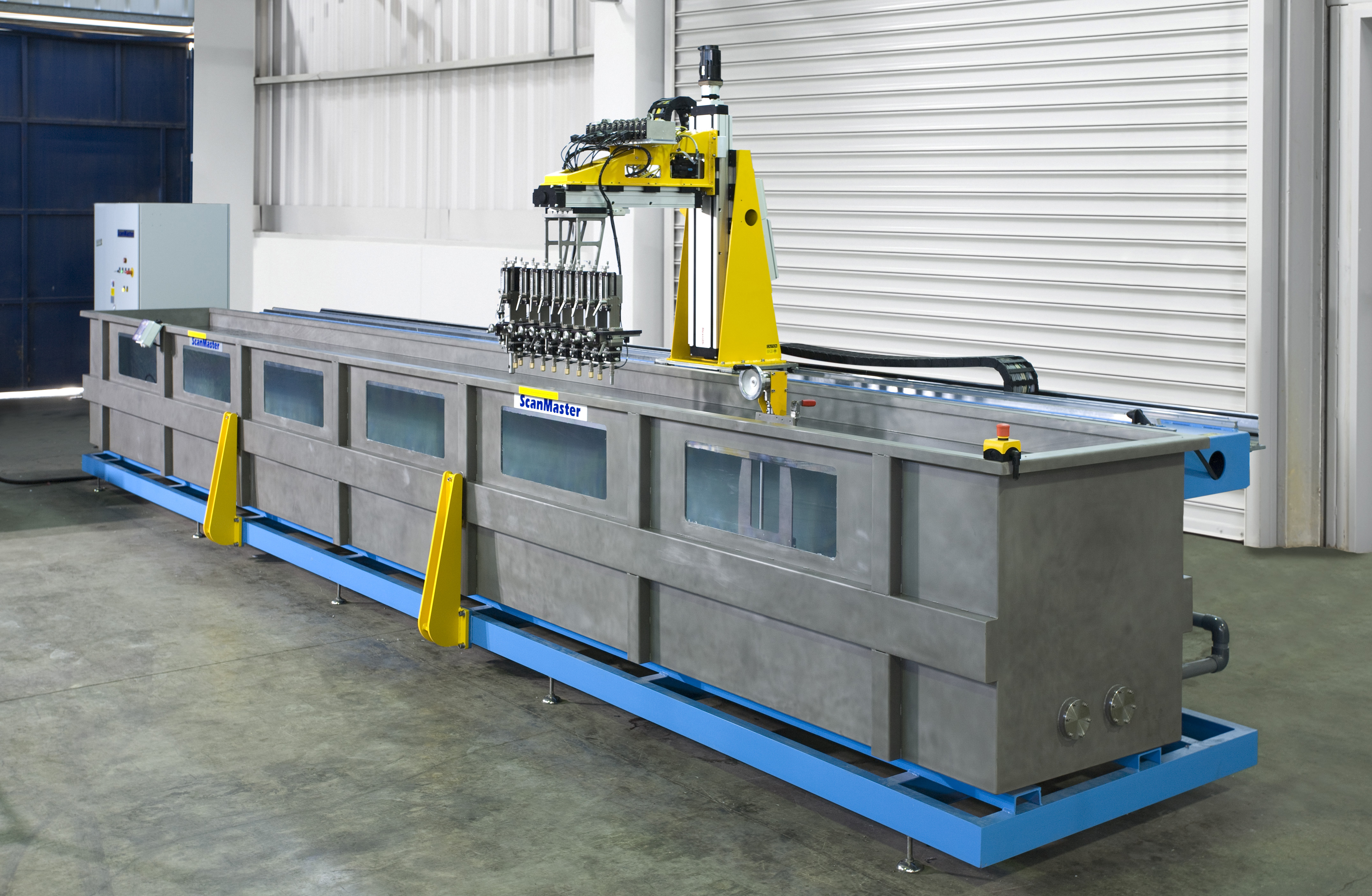
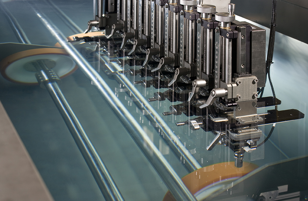
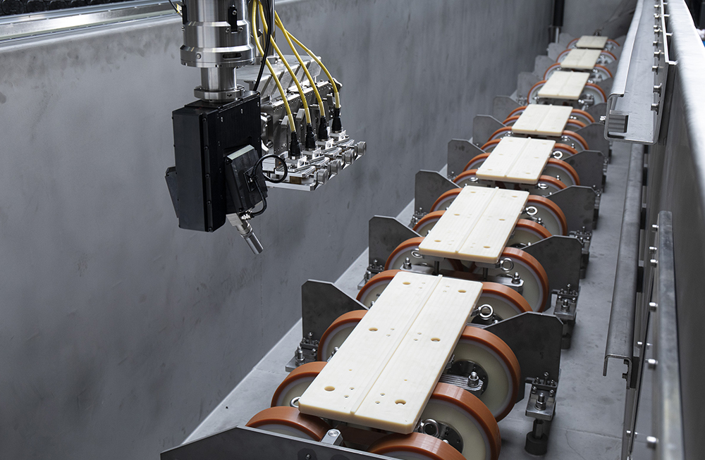
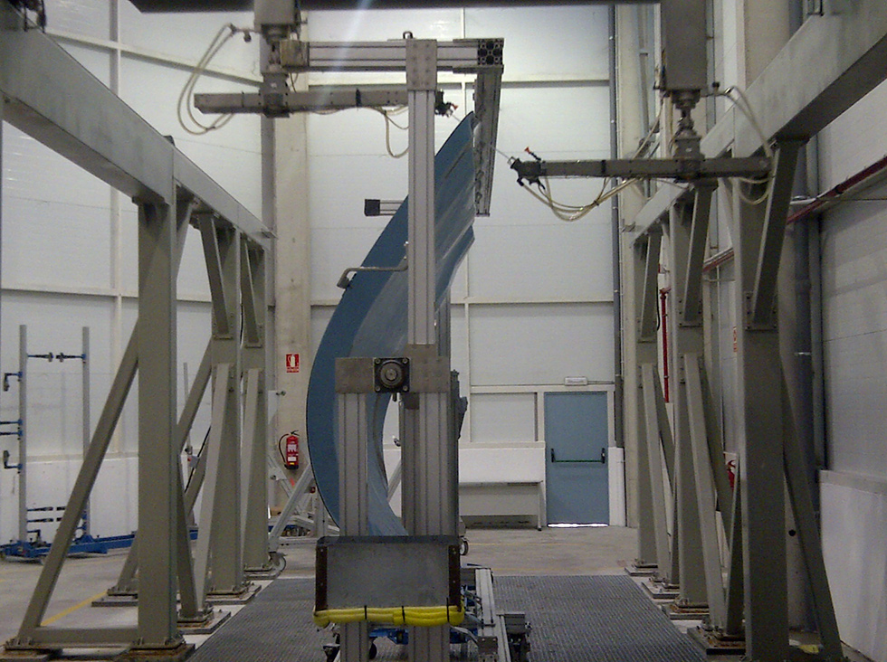
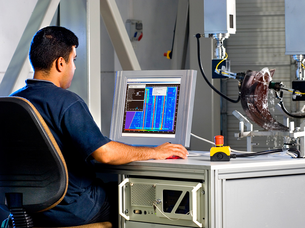
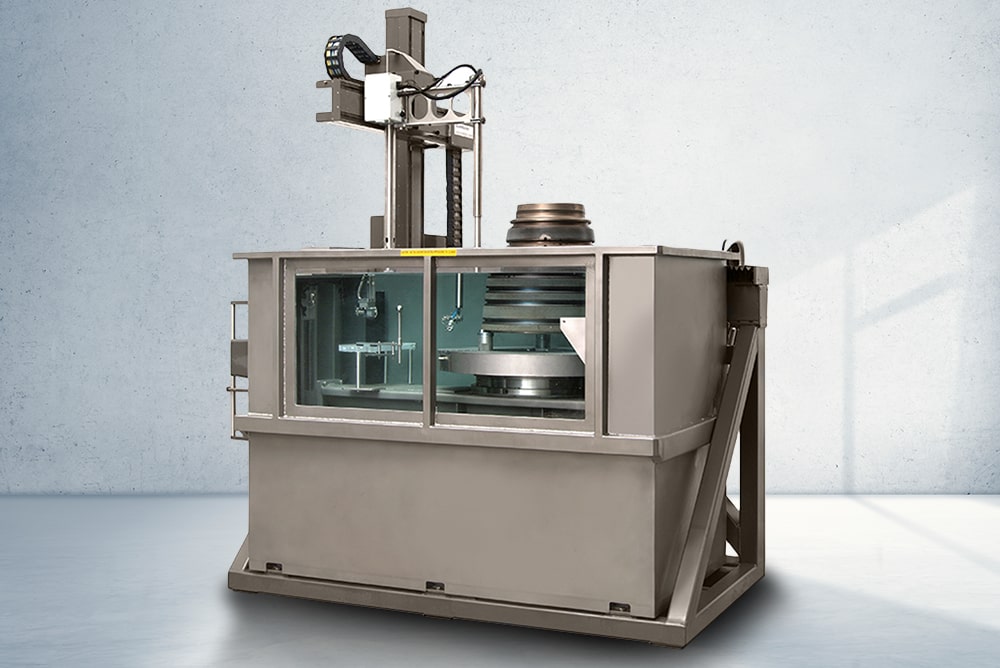
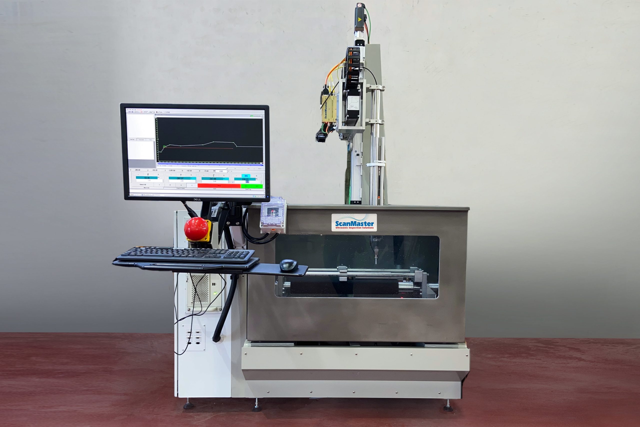
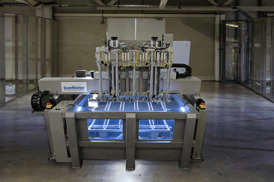
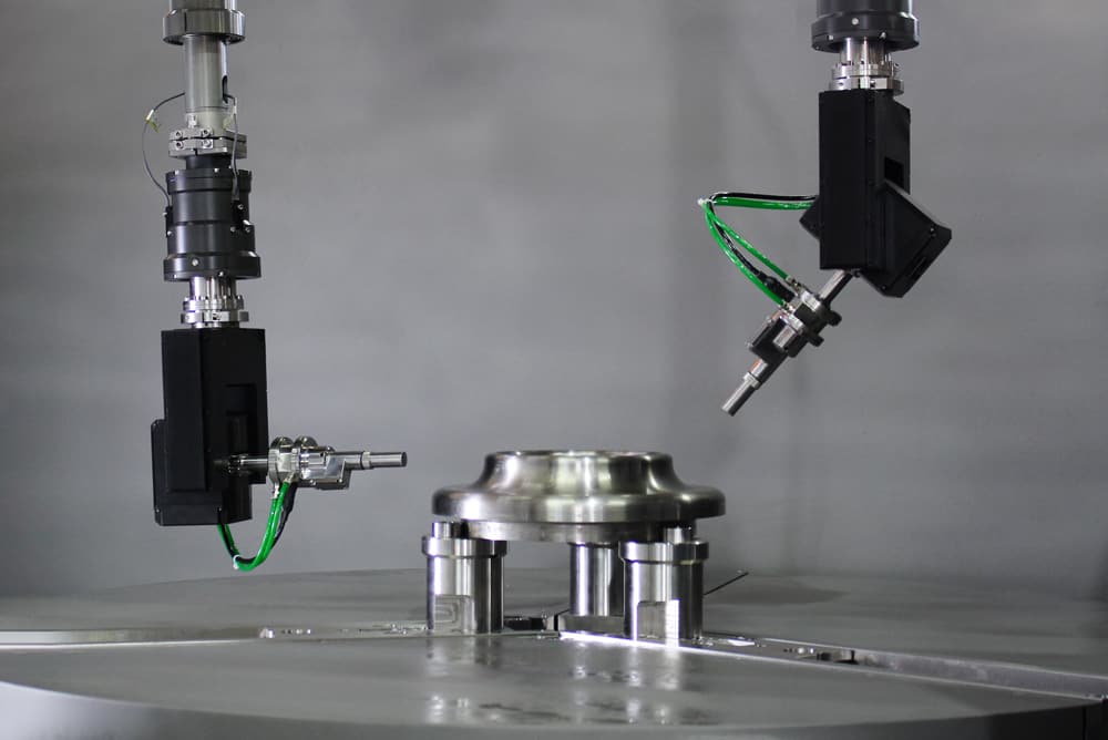
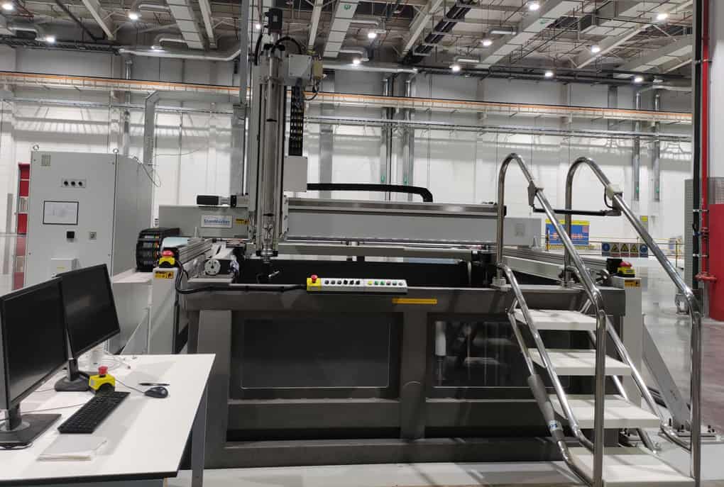
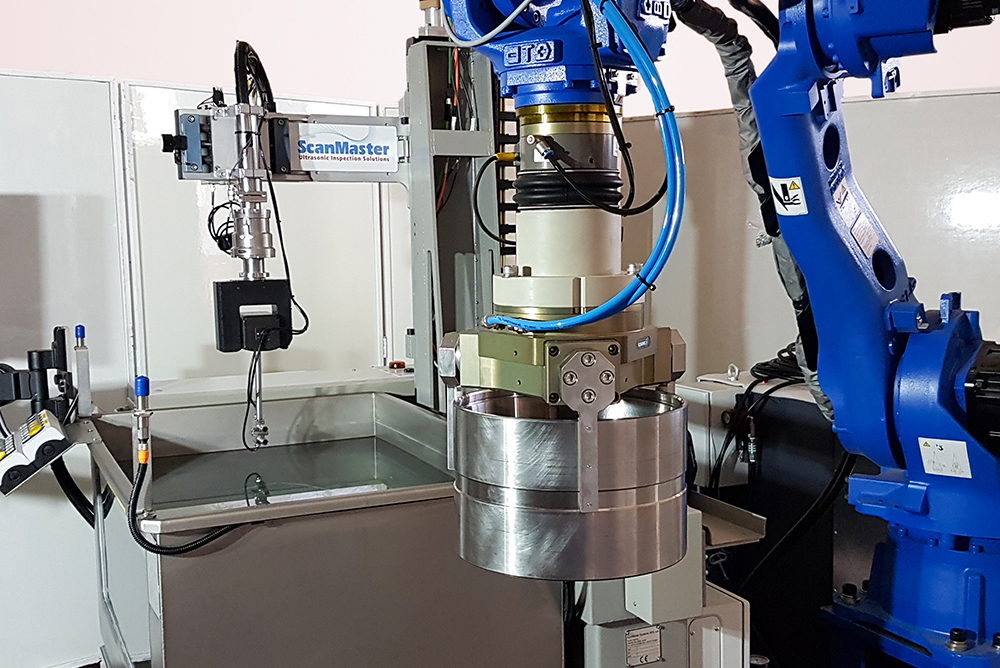
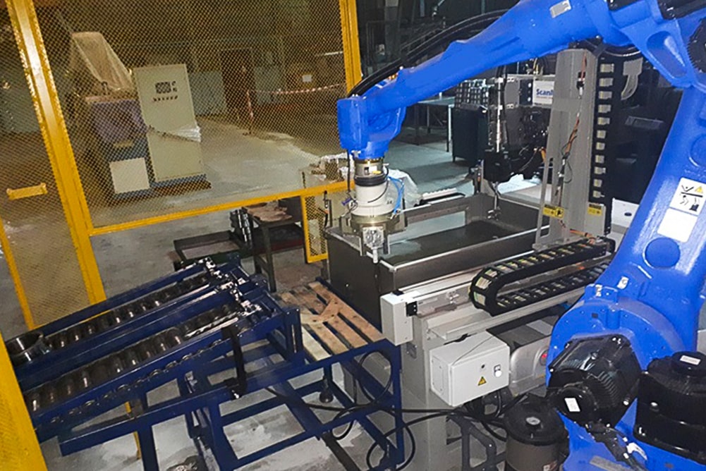
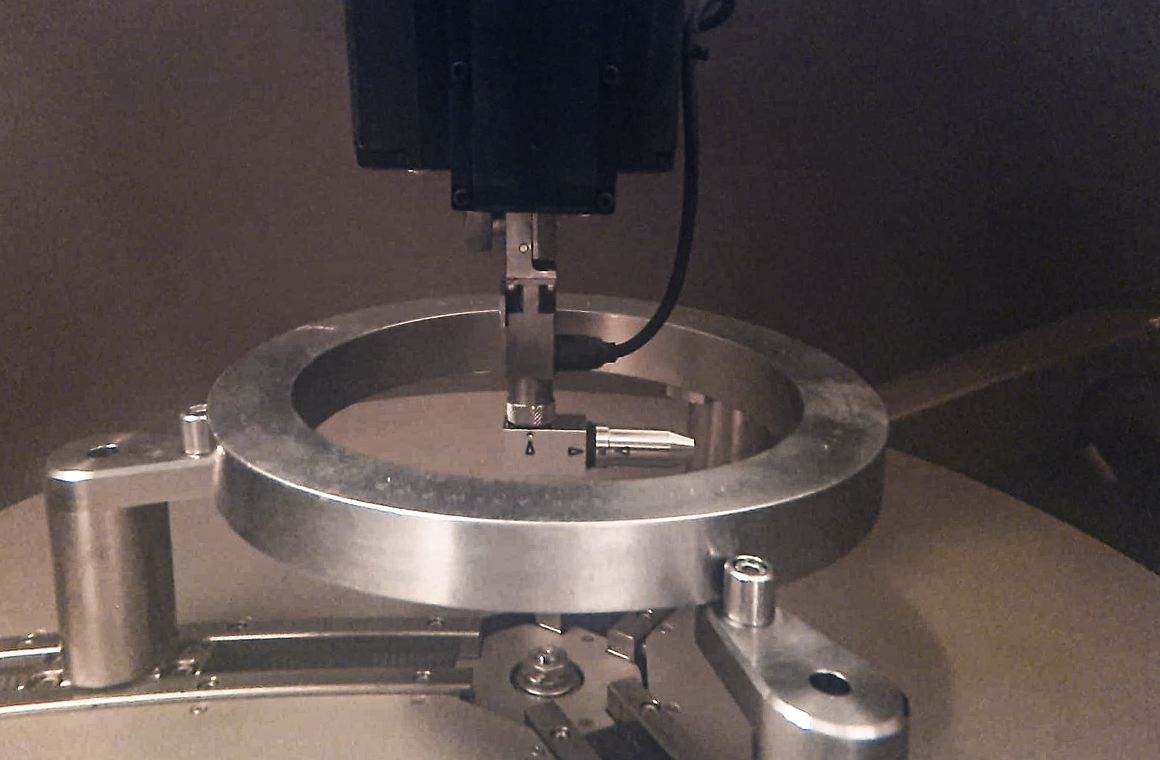
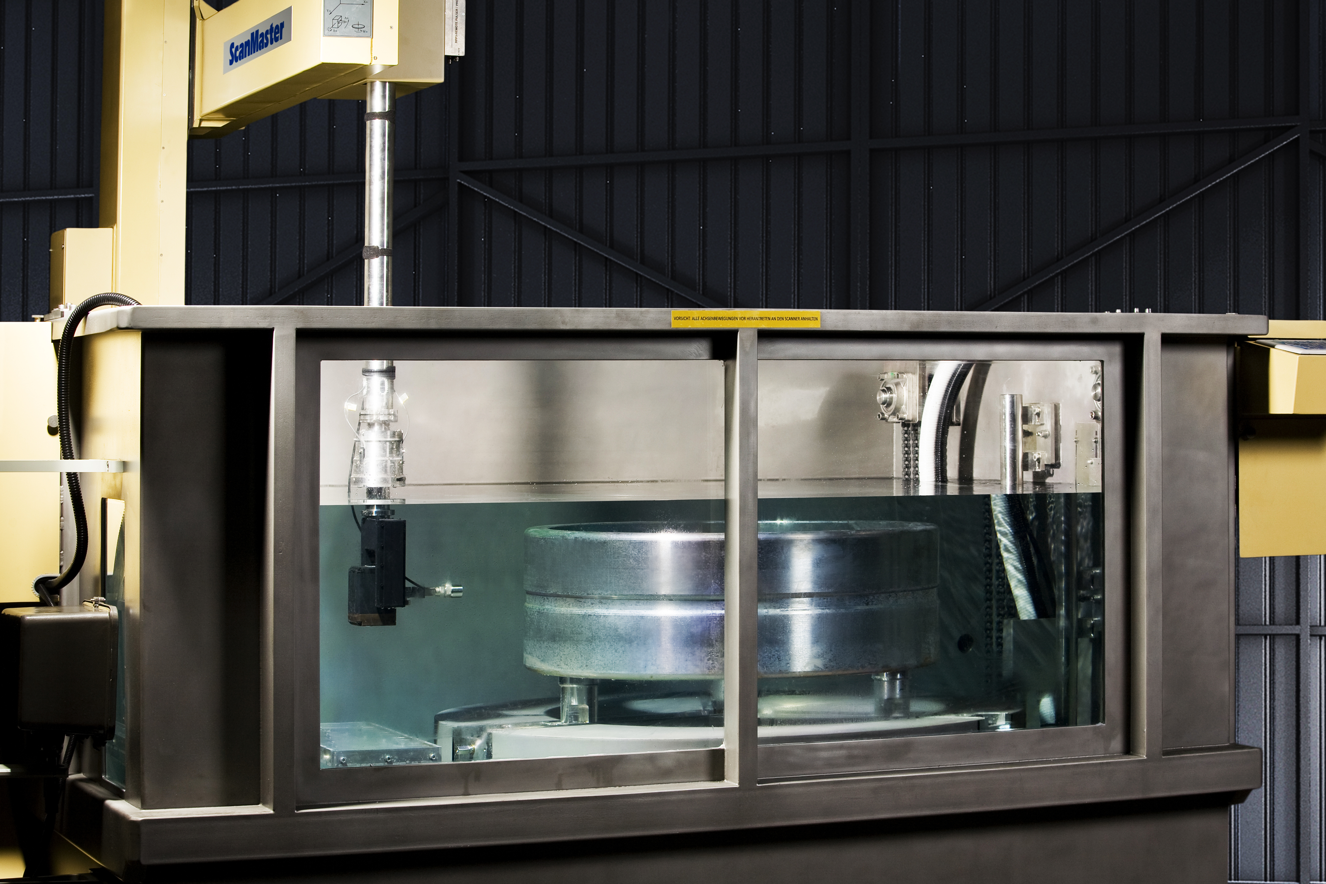
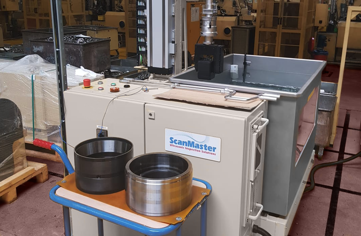
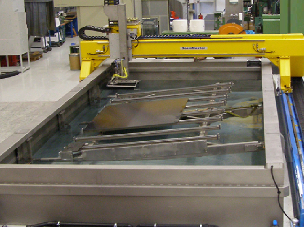
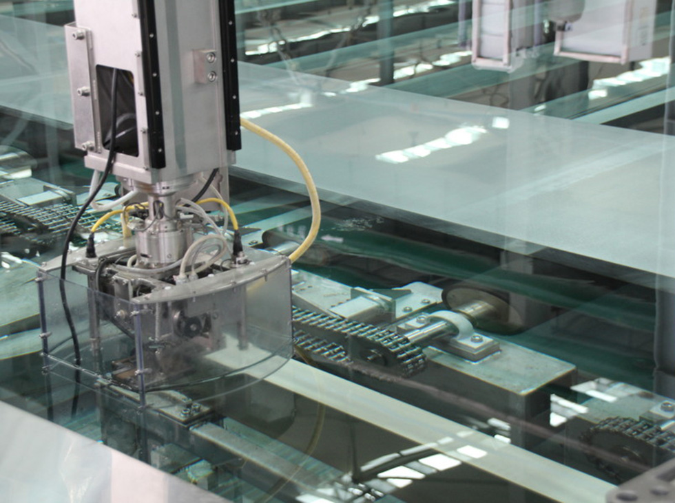
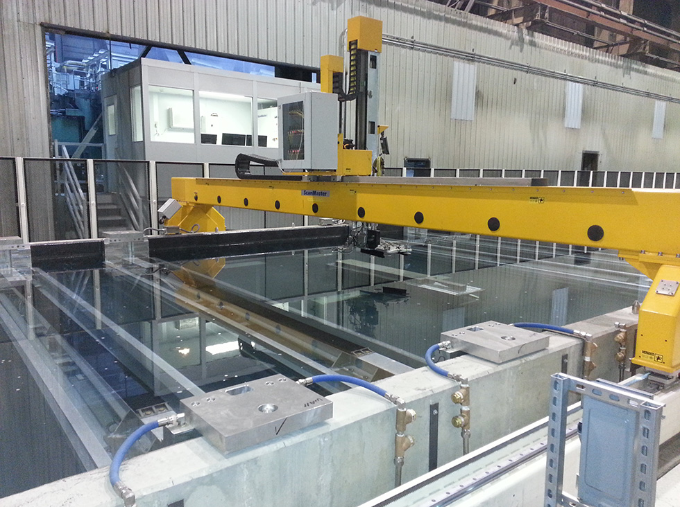
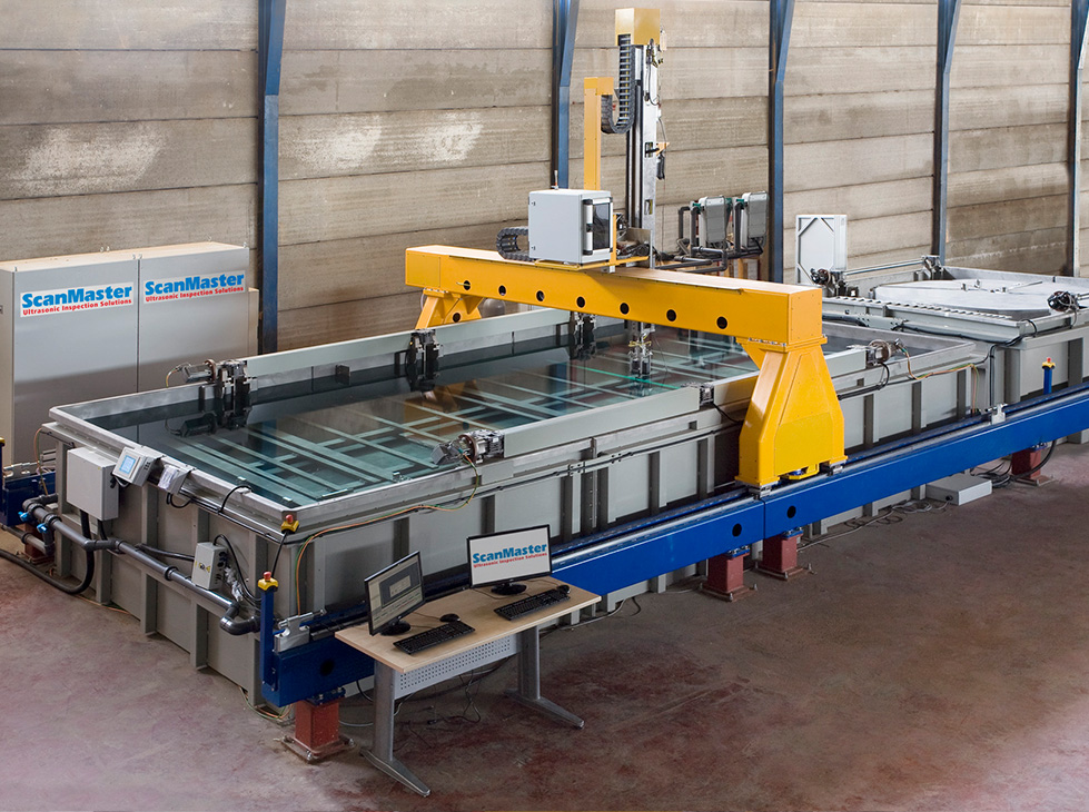
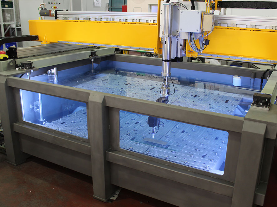
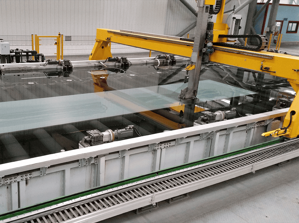
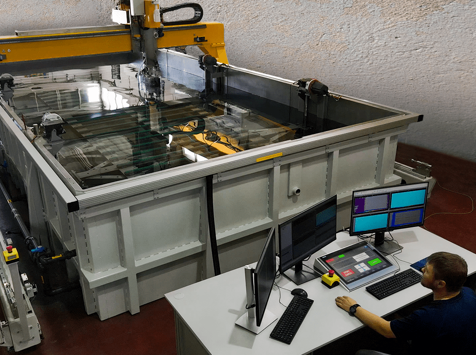
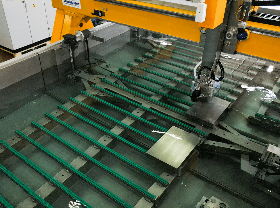
Ultrasonic Bearing Inspection: Systems Gallery


Features and Benefits
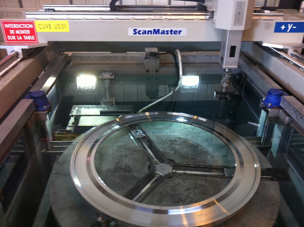
- Rugged immersion tanks with high-precision mechanics
- chucking and centering of the rings
- Fast two-position lifting device (operated from the HMI screen) for easy loading and unloading of bearings
- Motorized turntable chucks for automated
- Provision for interfacing with a loading-unloading robot
- Multi-transducer probe holder for increased inspection throughput
- Fully automated inspection process requiring no operator intervention maximizes efficiency and helps prevent operator errors
- Efficient "Teach-In" function for programming of spherical and ball bearings
- Off-line part programming through importing part models from CAD files
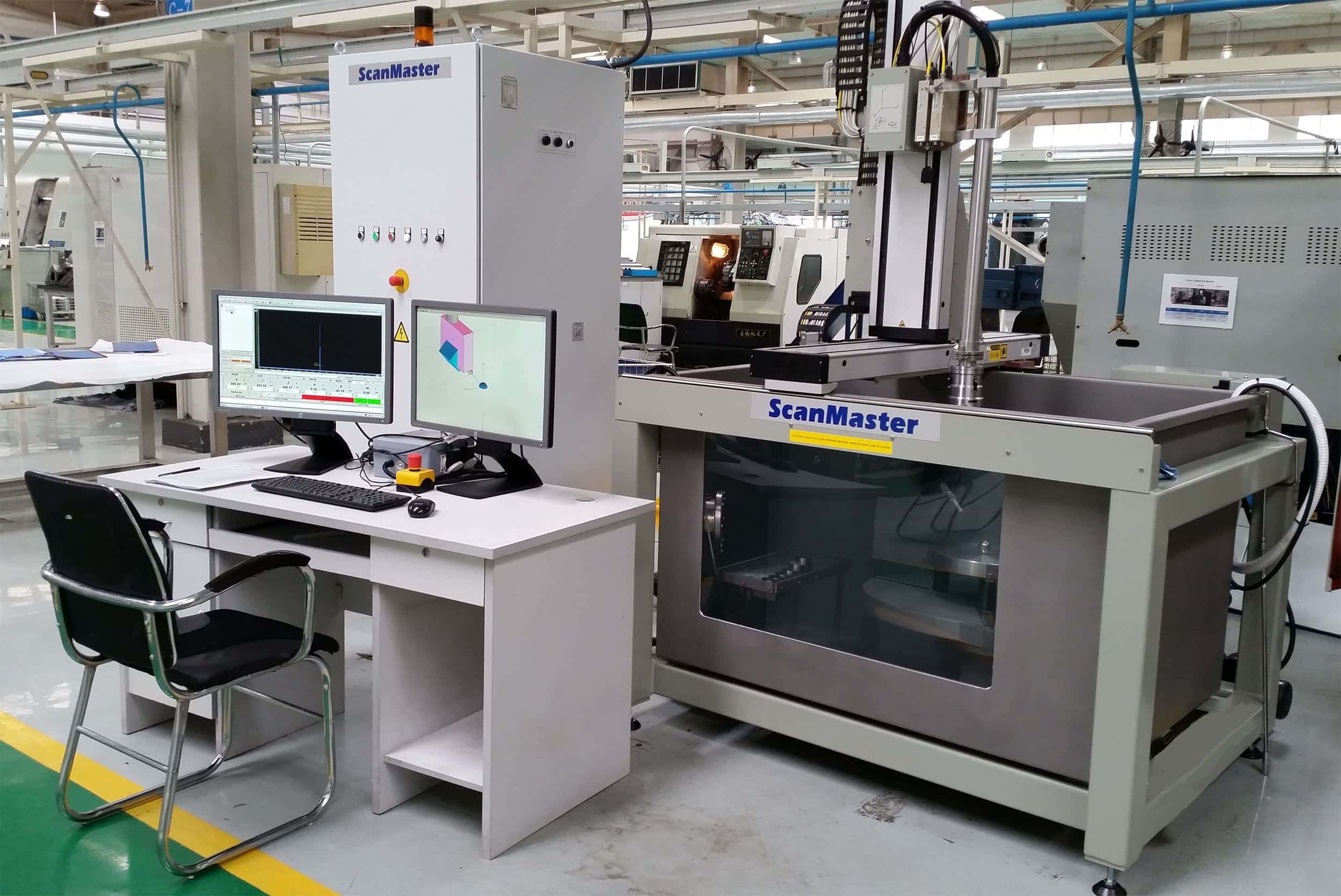
- A, B, and C-scan data analysis tool kit, including a tool library for analysis and evaluation of scan results
- 3D display of bearing model and scanning robot
- Comprehensive inspection reports with standard and customized versions
The Crucial Role of Ultrasonic Inspection in Bearing Manufacturing
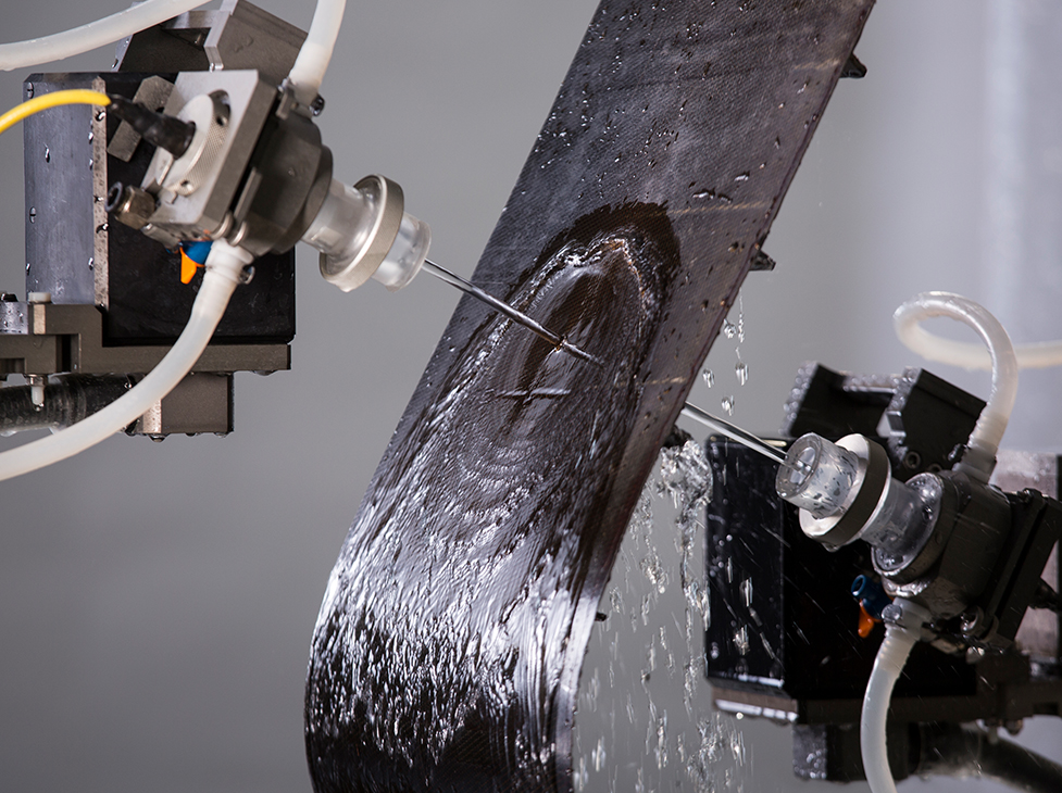
Ultrasonic inspection plays a pivotal role in ensuring the reliability and performance of bearings, a critical component in various machinery and equipment. By utilizing advanced ultrasonic testing techniques, potential defects in bearings can be detected without causing any damage to the components.
The significance of ultrasonic inspection for bearings lies in its ability to identify hidden flaws, such as cracks, or material defects, with high accuracy and precision. Ultrasonic waves are used to penetrate the bearing material, providing detailed information about the internal structure and integrity. This allows maintenance teams to proactively detect and address potential issues, preventing costly downtime and minimizing the risk of equipment failure.
By prioritizing ultrasonic inspection of bearings, industries can enhance operational safety, reduce maintenance costs, and increase productivity. It is an indispensable tool for ensuring the reliability and efficiency of rotating machinery in diverse sectors, including manufacturing, power generation, transportation, and more.


")
")