Rail Ultrasonic Testing

Ultrasonic Rail Testing

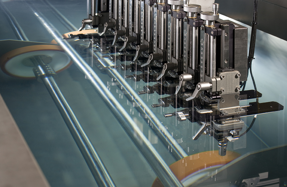
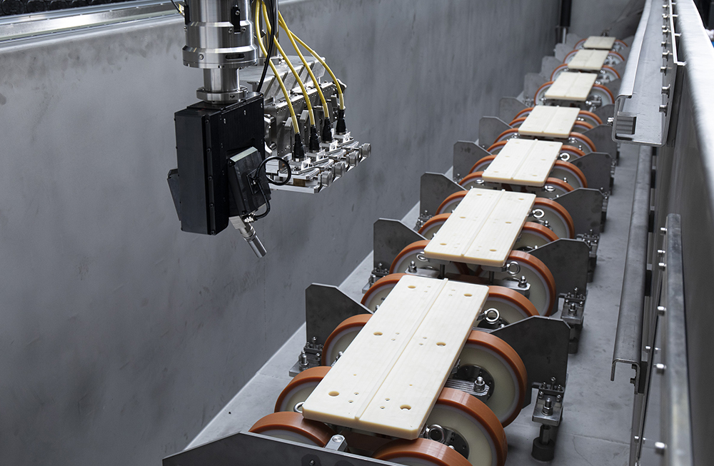
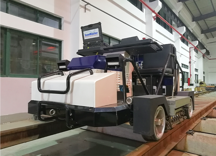
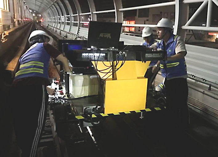
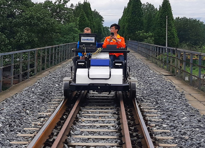
The new UT-M18, an inspection system mounted on a self-propelled electric trolley, is the latest addition to ScanMaster's product line for ultrasonic rail testing of in-situ metro and underground railways. The innovative sled structure of the UT-M18 enables simultaneous ultrasonic inspection of both rails using multiple probes for maximal coverage of the rail profile. An advanced self-alignment module maintains sled positioning in all track scenarios, ensuring reliable automatic inspection.

The rail height monitoring mechanism automatically adjusts relevant ultrasonic settings when a change in rail type is detected. The system is capable of inspection at speeds of up to 20 km/h. Results are presented in real time in B-scan display.

metro rail ultrasonic testing

The UT-M18 features 18 ultrasonic detection channels. The system’s unique capabilities include:

  • Innovative unique “wear free” probe housing design
  • Optional integrated GPS for defect localization
  • Easy mounting / demounting of the trolley from the rail in 20 minutes or less
  • Exclusive water flow mechanism designed to minimize water usage
  • Unlimited ability to cross above rail switches and intersections
  • Easy “zero cost” maintenance
  • Minimal power consumption allowing for extended overall system operation

Ultrasonic Rail Testing: Systems Gallery

Ultrasonic Rail Inspection
Rail Inspection
Rail Ultrasonic Testing

The TrackMaster

The UT-M18 is delivered with integrated TrackMaster software, a complete package for data collection, presentation and analysis. The software covers all phases of system operation, from configuration and inspection to post-processing. Data can be processed in both offline and online modes. In addition, data records can be used to establish a baseline for comparative periodic monitoring of rail conditions.

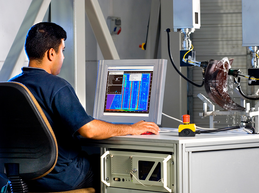
The analysis function is used to identify and categorize flaws in a scan. It is based on a defect finder algorithm with an integrated noise reduction algorithm or/and an integrated AI/Fuzzy Logic algorithm. Using this analysis features eliminates the need for specially trained personnel and reduces the total cost of system usage.

The analysis module enables the issue of a report containing a list of all suspected flaws, their locations in the scanned track and the distance from the nearest reference points.

rail ultrasonic testing

This report is useful to the repair teams responsible for locating detected flaws on the relevant section of rail and performing required maintenance operations.

What is ultrasonic testing of rails

Ultrasonic testing of rails is a non-destructive testing (NDT) method that uses high-frequency sound waves to detect defects in the interior of rails. The sound waves are transmitted into the rail and reflected back if they encounter a defect. The reflected sound waves are then analyzed to determine the size, location, and nature of the defect.

Ultrasonic testing is a very effective method for detecting defects in rails, such as cracks, voids, and inclusions. It is also a relatively safe and quick method, making it ideal for inspecting large lengths of rail.

Ultrasonic testing of rails is typically performed using a portable ultrasonic testing device. The device is equipped with a transducer that generates the sound waves and a receiver that detects the reflected sound waves. The transducer is placed on the surface of the rail and the sound waves are transmitted into the rail. The receiver then collects the reflected sound waves and sends them to the device's computer for analysis.

The computer software analyzes the reflected sound waves to determine the size, location, and type of the defect. The software can also create an image of the defect, which can be used to plan repairs.

Ultrasonic testing of rails is an essential NDT method for ensuring the safety of railway tracks. By detecting defects in rails before they cause a failure, ultrasonic testing can help to prevent derailments and other accidents.

Axles and Wheels Inspection

Axels and Wheels Inspection

As stringent regulations are imposed on train wheel and axle inspection in both the manufacturing and service sectors, the industry requires automated inspections that provide efficiency, quality, repeatability, and documentation of test results.

ScanMaster offers a wide range of automated inspection systems for testing of wheels, axles and wheel-set assemblies in both production lines and refurbishing shops.

axels-and-wheels-1
axels-and-wheels-1

Axels and Wheels Inspection

As stringent regulations are imposed on train wheel and axle inspection in both the manufacturing and service sectors, the industry requires automated inspections that provide efficiency, quality, repeatability, and documentation of test results.

ScanMaster offers a wide range of automated inspection systems for testing of wheels, axles and wheel-set assemblies in both production lines and refurbishing shops.

The AS-220w Series Wheel Inspector includes fully computerized ultrasonic systems for inspection of train wheels suited for production line or refurbishment shop.

The AS-220a is ScanMaster's series for axle inspection in production line and refurbishment shop environments. This series provides full automation of the inspection process in a cost effective manner.

Axels and Wheels: Systems Gallery

Standard 2
Standard 3
Standard 4

Features and Benefits

  • Phased-array UT, conventional UT or a combination of both technologies
  • High throughput, multi-shift operation in industrial environments
  • Simple to use, single-screen operator control console
  • Advanced analysis tools with projection views and suppression of falls indications
  • Detailed test result documentation for reporting and archivin
plate inspection

Plate Inspection

Plate Inspection

Rolled aluminum and titanium plates intended for aerospace applications are inspected in accordance with stringent industry standards. The large size of the plates and their wide thickness range demand high inspection productivity. Defect evaluation and comprehensive inspection reports are common requirements.

ScanMaster offers a variety of field proven, high throughput plate inspection systems designed to provide a complete solution for material testing and handling. ScanMaster systems use either phased array or conventional transducers for defect detection, and include advanced features for plate scanning, data acquisition, defect evaluation and reporting.

Plate Inspection: Systems Gallery

Standard 2
Standard 3
Standard 4
Standard 1
Standard 5
Standard 6
Baoti1
נשםאן5
Baoti3

Rolled aluminium plates intended for aerospace applications are inspected in accordance with stringent industry standards, such as the AMS-STD 2154, the ASTM B594 and the Boeing BAC 7055.  The large size and considerable thickness of the plates demand high inspection productivity. Defect evaluation and categorization, comprehensive inspection reports, and interfaces to various MES (manufacturing execution system) types are common requirements.

Automation of standart-driven functions:

  • Non-contact surface tracking
  • Automated UT calibration and verification procedures to reduce pre-scanning time
  • Generation of beam profile data for accurate sizing of defects
  • A configurable defect evaluation procedure complying with applicable standards, using a fully automated rescan
  • Automated defect classification and sizing

The System

The inspection system design is based on a loading roller table, from where the plates are transported onto the lifting platform and immersed into the tank. After inspection, the plates are lifted up and proceed through the dryer to the unloading table.

UT inspection is done in immersion based pulse-echo mode using two 128 element phased array transducers that scan simultaneously with the required overlapping.

plates right size for web
2

Automated UT calibration and verification procedures to reduce pre-scanning time

Sensitivity calibration and verification procedures are among the most time consuming processes of UT inspection.

The initial stage involves setting the uniformity of the virtual probes’ (VP) ultrasonic beams across the depth, using a reference block with side-drilled holes of different depths. As the system operates with two probes, this procedure is extremely important.

Once VP uniformity is achieved, Distance Amplitude Correction (DAC) calibration and verification is automatically performed for a single VP by dynamically scanning a designated set of calibration standards. Once the DAC is created, the system automatically updates it in all setups, as necessary. The sensitivity check (dynamic check) is usually done every four hours and is executed automatically.

Automatic inspection procedure

1. The Main Scan

The main scan begins after the plate is inside the tank and the "Clearance" command is received.  The main scan is done using a UT setup for the required inspection class. C-Scan images of the material gate and back-wall gate (with separate attenuation mode) are collected.

Based on this scan, the software generates an intermediate report that shows detected indications on the C-scan. The Indications table of the report includes details about the location, amplitude and ToF of each indication, and provides a preliminary list of indications with defect categorizations according to the guidelines of the relevant standard.

Mask group

2. Indications rescan

Following the main scan, some of the indications found in the plate need to be rescanned.

According to ASTM B594 2.2.1 and 10.5.1 specifications and Boeing specifications, all indications exceeding a predefined level of the adjusted reference size must be inspected by means of angle manipulation. This evaluation is done by angulation and movement of the sound beam around the indication.

In systems based on conventional UT probes, this inspection is generally done using a probe manipulator that mechanically rotates the probe. In the system described in this paper, the phased array probe performs the procedure using a combination of electronic sectorial and linear scanning.

The procedure generates a combined "Top C-Scan".

Defects can be evaluated one at a time, or automatically (as a set). Following the evaluation process, the Indications table is updated with the maximum acquired amplitude of the defect and its proper categorisation.

Mask group (1)

Plate Surface Tracking

Due to the production process of these plates, there may be occasional slight waviness of the plate surface that affects the UT refraction angle. Misalignment of plate placement relative to the scanning gantry may also affect the relative position of the plate surface to the transducers’ scanning plan. To prevent misalignment issues from influencing the UT data, the system tracks the surface of the plate during scanning, using a specially designed surface tracking subsystem.

Distance monitoring is based on measurement of the water path of each of the three probes to the inspected surface. A designated software algorithm monitors the distance and calculates the offsets to be applied to the azimuth or elevation axis of the manipulator. In addition, the software generates the necessary offset to be applied to the Z axis in order to maintain the water path within a predefined tolerance.

Use of the surface following algorithm does not affect scanning speed.

In order to utilize the full scale of the system scanning envelope while maintaining high productivity, the system supports inspecting multiple plates of the same thickness in one scan. During the multi-plate full scan, one C-scan of all the plates scanned in a batch is produced. After the scan is finished and the overall C-scan has been completed, the software automatically divides the overall C-Scan into separate C-scan files of each plate. To prevent data loss, the division is done using an edge recognition algorithm. The separate C-Scans therefore include part of the edge and the stretcher marks (if any).

The operator may define the ROI (Region of Interest) of a C-scan of an individual plate to define an area in which defect evaluation will be done. From this point, each plate is evaluated separately, and an individual report per plate lot number is issued.

Mask group (2)

Features and Benefits

  • ‘One stop shop’ providing fully integrated, high throughput automated inspection systems.
  • To provide a comprehensive inspection solution, systems may include material handling devices such as lifting platforms and rolling tables in addition to the immersion tank and scanning robot.
  • Full communication with plant computer for material handling, transfer of material information and test requirements, and handover of inspection results.
  • Advanced, unique features assure accurate scanning, reliable data acquisition and automated defect evaluation, as well as high inspection throughput.
  • Automated DAC calibration to reduce pre-scanning time.
  • Non-contact surface tracking to ensure perpendicularity of the ultrasonic beam on the plate surface.
  • Automated defect evaluation procedure complying with applicable standards.
  • Compliance with major standards, such as AMS STD 2154, ASTM B 594, ASTM E 2375, BSS 7055 and ABP-6-5232.

Billets and Bars Inspection Systems

Ultrasonic Testing of Bars and Billets

ScanMaster offers a variety of immersion scanners for ultrasonic testing of round and square bars and billets, as well as tubes and shafts intended for use in aerospace, steel and other industries.

These ultrasonic bar testing systems can support a wide range of part dimensions, accommodating bar diameters of 8 mm –
1,000 mm (5/16" – 40") and different bar lengths, according to customer requirements.

Both conventional and phased array transducers are incorporated in such scanners. System configuration is depending on the geometry and size of products to be inspected, as well as on the applicable standards and specifications of requirements. Custom design assures full system compliance with specific geometrical parameters and inspection requirements.

Ultrasonic Bar Testing: Systems Gallery

Standard 2
Standard 3
Standard 4
Standard 5
Standard 6
Standard 7

Supported Scanner Configurations

ScanMaster ultrasonic bar testing systems support a number of scanner configurations.
The implemented configuration is based on the geometry and size of products to be inspected as well as
on applicable standards and specifications of customer requirements.

Some supported configurations include:

  • Search tube with gimbal/gimbal probe manipulator supporting quick exchange between conventional
    and Phased Array transducers
  • Multi transducer heads with surface following mechanism for:
    a. Multi Zone inspection with either single element or Fermat probes
    b. Combined composite scan using multiple transducers to enhance productivity
    c. Probe adjustment allowing combinations of shear scan in circumferential and axial mode
  • Dedicated rotator for calibration bars
ultrasonic bar testing system

Other configurations that support devices such as bar indexers, drop-in platforms for flat parts and more can be provided.
Add-on jigs for accommodation of rectangular and square bars of various dimensions are also available.

Features and Benefits

  • Modular configuration, both hardware- and software-wise
  • Adherence to major aerospace and steel standards: AMS 2628, P3TF31, DMC 0022, SIM-16, RPS 707, ASTM E-588, SEP 1927 and others
  • Rugged immersion tanks with high-precision mechanics and integrated water circulation system
  • Universal inspection head permits multi-zone or conventional inspection, as applicable
  • Customized multi-transducer holder for simultaneous inspection using longitudinal and shear waves
  • Quick exchange between phased arrays and conventional transducers
  • Mechanical surface follower
bar testing
robot bar testing ultrasonic
  • Multi-channel programmable ultrasonic instrument with exceptional performance
  • Helical (spiral) scan mode used for inspection of round bars and billets significantly increases inspection throughput
  • A, B and C-scan data processing and analysis tool kit. Includes a reach library of tools for analysis and evaluation of scan results
  • Comprehensive inspection report, standard and customized versions in accordance with applicable aerospace and steel standards: ASTM E-588, SEP 1927 and others
  • Automation of major functions provides time savings and prevents operator errors
ultrasonic inspection of composite

Ultrasonic Inspection of Composites

Ultrasonic Inspection of Composites

The extensive use of glass and carbon fiber composites in manufacturing of modern aerospace components is raising the need for reliable, cost-effective NDT systems for the ultrasonic inspection of such components in the manufacturing stage.
The complexity of the new multilayered parts of complicated geometry with high curvatures and varying thicknesses and the requirement to inspect the parts on a 100% rate are posing serious challenges to such systems.
For example, stringer webs, flanges, edges, radii and chamfers as well as untrimmed part and parts drilled with holes must be completely inspected.

Ultrasonic Inspection of Composites: System Gallery

Standard 2
Standard 3
Standard 4
Standard 1
Standard 5
Standard 6

Supported Scanner Configurations

Travelling bridge type scanners

suitable for inspection of single curvature parts (one bridge systems) or double curvature parts (two bridge systems). This configuration requires minimal floor space and permits use of a turntable for high throughput inspection of round structures. A removable immersion tank can be provided as required.

Dual tower scanners

appropriate for scanning complex double curvature parts. A removable immersion tank can also be provided in this configuration.

Flatbed systems

used for inspection of flat parts or parts of moderate curvature. These scanners of ultrasonic inspection of composites, are usually equipped with multiple squirters for productivity enhancement.
Parts of complex shape can also be inspected by squirter systems using industrial robots.

Features and Benefits

  • Fully integrated systems: All system components are designed, manufactured and tested by ScanMaster, ensuring smooth, reliable operation of the system as a whole
  • Scanning speeds of up to 1,000 mm/second
  • Simultaneous inspection in through transmission and pulse echo modes
  • Simultaneous inspection with linear and logarithmic amplifiers
  • Dual squirter, dual frequency features for high throughput
  • Easy part programming through intuitive Teach In tools, including import of CAD files such as CATIA
  • Advanced image analysis and processing tools
  • Adherence to Airbus and Boeing requirements
  • Packaged water systems with active flaw control, including storage, filtration and UV treatment
  • Optional turntable and part fixtures
  • Optional removable immersion tank (gantry and dual tower configurations)

LS-200 COPA

Phased Array Immersion Scanner for Automatic Ultrasonic Inspection of Composite Panels, Skins and Stringer Components

The extensive use of glass and carbon fiber composites in manufacturing of modern aerospace components is raising the need for reliable, cost-effective NDT systems for the inspection of such components in the manufacturing stage. The complexity of the new multilayered parts of complicated geometry with high curvatures and varying thicknesses and the requirement to inspect the parts on a 100% rate are posing serious challenges to such systems. For example, stringer webs, flanges, edges, radii and chamfers as well as untrimmed part and parts drilled with holes must be completely inspected.

ScanMaster LS-200-COPA immersion scanners provide an efficient, automated solution for the ultrasonic inspection of Carbon and Glass-Fiber-Reinforced Polymer parts, such as skins, stringers, and spars. The
inspection is making use of multi-channel ultrasonic phased array (PA) technology, which is well proven for such applications.

ls-200 copa

What is water jet ultrasonic inspection?

Water jet (squirters) ultrasonic inspection is a cutting-edge technique utilized for the meticulous examination of composite materials. Particularly suitable for dense materials and those with significant sound dissipation properties, such as glass fiber composites, this method has become the industry standard for inspecting such composites. By employing water jets coupled with ultrasonic waves, this non-destructive testing approach allows for thorough through-transmission inspection. It is highly effective in detecting internal defects, delaminations, and anomalies that may compromise the structural integrity of composite materials. Whether it's examining buoyant composites or components vulnerable to water ingress, water jet ultrasonic inspection provides unparalleled accuracy and reliability, ensuring the highest quality and safety standards in various industries, mainly for aerospace manufacturing.

ScanMaster